|
HANG ZHOU TAI LIAN CRYOGENIC EQUIPMENT CO., LTD.
|


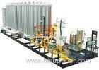
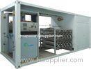
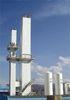
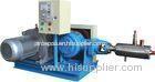
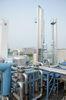
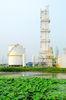
High Capacity 300m3/h 99.999% Pure Water Hydrogen Generation Plant
| Place of Origin: | Zhejiang, China (Mainland) |
|
|
|
| Add to My Favorites | |
| HiSupplier Escrow |
Product Detail
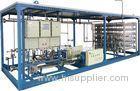
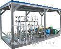
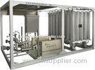
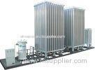
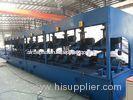
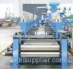
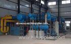
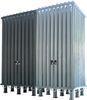
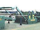
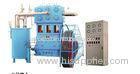
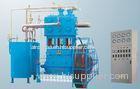
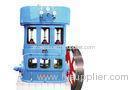
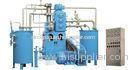
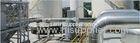
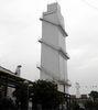
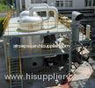
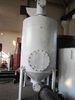
99.999% purity 300m3/h Hydrogen Generation Plant
Specifications:
Raw water (pure
99.999% purity 300m3/h Hydrogen Generation Plant
Specifications:
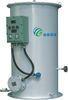
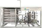
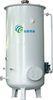
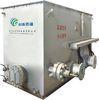
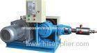
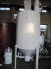
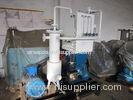
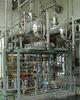
Raw water (pure water) is delivered to water tank. It goes through valve via the pipe and is fed to H2 and O2 tower by complementary pump. Then it goes through H2 and O2 separator in lower part of the pipe and through alkali liquid recycling pump , alkali liquid filter to electrolyzing tank. H2 and H2 are obtained by electrolyzing. O2 and H2 through pipe to alkali liquid for cooling and H2 and O2 separator comprehensive column cooling and washing(H2 needs to be cooled further). Moisture is separated through water-gas separator and goes through water discharger to be drained. O2 through O2 pipe goes to adjusting pipe to be delivered out. According to customer’s requirement to be vented or stored. H2 from H2 comprehensive column and delivered after adjusted.
Cooling water of system is mainly supplies electrolyzer , silicon rectifier penal , and for water sealing purpose for the tank.
Instrument air resource separately supplies for primary instrument and valves in frame I of electrolyzing equipment.(pneumatic diaphragm adjusting valve, primary instrument valve in H2 purifier equipment).
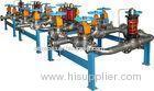
4.2 Technology process for electrolyzing equipment:
4.2.1 H2 and O2 system:
Pure water in electrolyzing tank is decomposed under DC action. In the cathode and anode plates in cabin H2 and O2 are created separately which flow out of the two poles in electrolyzing tank in the cabin with alkali liquid.
Through external pipes they go together and enters alkali liquid separator. H2 an O2 in the middle of separator (under alkali liquid surface) under gravity ,H2 (O2 ) and alkali liquid descends separately to separate H2(O2) which is cooled on the upper part of the separator and washed. H2,O2 remove the dropping liquid on the top of the separator and O2 is vented to the atmosphere after adjusted valve. H2 is further cooled through comprehensive column to be saturated to gas-water separator for removal of dropping liquid. It is adjusted by pneumatic valve to Frame I.
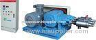
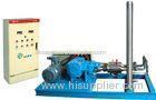
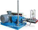
4.2.2 Alkali liquid recycling system (alkali liquid recycling )
H1 and O2 from electrolyzing tank in alkali liquid under gravity in separator they separate into H2 and O2.IT is cooled down in lower part of separator. They (two branches) flow into alkali liquid recycling pump. Pump provides the energy for alkali liquid recycling.. We adopt recycling pump to ensure the stable operation for the whole system. Alkali liquid goes through filter which removes the mechanical impurity by asbestos cloth to lower part of electrolyzing tank. It goes evenly through pipes to be distributed to each electrolyzing cabin. Electrolyzing liquid flows to each small cabin (between two poles) from lower part to upper part to be electrolyzed so that form inner recycling system in electrolyzing liquid.
4.2.3 Water complementary system:
Raw water is complemented by water supplementary pump to comprehensive column through washing sector to wash H2 or O2. Washing sector is water of sealed structure. Extra complementary water through flooding pipe to lower part of separator with alkali liquid to alkali liquid to alkali liquid recycling system to achieve purpose of water supplementary. Water pump working is interrupted which start and stop is controlled by alkali liquid surface for H2 and O2 separation.
4. 2.4 Cooling water supply system
It is divided into two branches,one through pneumatic diaphragm adjusting valve into H2 (O2) alkali liquid cooler cooling recycling alkali liquid so as to control system working tempt. purpose and another separately into H2(O2) comprehensive column to cool the H2(O2).
4.2.5 Nitrogen system
This equipment has nitrogen filling opening pipe, through valve in alkali liquid conflux pipe of H2 and O2 separator to fill the system with nitrogen for blowing out and gas tightness at starting.
Blow up and gas tightness test when the system first start and after repair.
Blow up and gas tightness test when H2 tank first start or after repair.
4. 2.6 Drainage system
Drainage opening for electrolyzing tank, alkali filter, alkali liquid tank and raw water tank, etc.
4. 2.7 Alkali entering (inlet water) system for H2 plant
H2 generating equipment consists of electrolyzing tank and Frame I., alkali liquid after filtering is filled to electrolyzing tank. When it is full, alkali liquid goes to H2(O2) separator. It is fit for starting.
Raw water is sucked with alkali liquid. It is fit when the system is under washing. 4.1.8 Alkali dosage system
Raw water in alkali tank is recycled by alkali pump. It goes through alkali filter, valve to be switched to alkali tank. During raw water recycling, add potassium hydroxide regularly which is not easy to be solved so that dosing alkali recycling(outside recycling) is formed. This work is executed when the equipment starts.
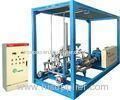
4.3. Description of the control system:
4.3.1,The supplier will provide PLC for hydrogen production system with full automatic operation. Which has auto stop and auto inspection and control. Each stage has warning, interlock function. It has one button to auto level. It also has manual operation function. When PLC has fault, system manual operation ensures the system to produce the hydrogen continuously.
4.3.2 Control system circuit and parameter collect point for hydrogen production
4.2.3. Pressure control system
Through pressure transformer at O2 separator side, pressure is measured and translated to DC signal of 4~20 mA to LC,by comparison with set value and PID calculation, and by electrical switcher to revert to 0.020.1MPa electric signal so as to control the opening of pneumatic diaphragm valve to obtain pressure stability of the system. System pressure is set on man-machine screen.
4.2.4 Liquid level control system
a. H2 separator level control
In process of electrolyzing, raw water is continuously consumed so that the level of water at O2 separator is continuously reduced. Thus it must be complemented by water complementary pump so as to satisfy the consumption of water.
Liquid level is measured through pressure differential transformer at the H2 side which is translated to standard 420mA electric signal to PLC Through comparison of set upper and lower liquid level limitations for warning and interlock to create signal to control start and stop, and interlock warning of the complementary pump. Upper and lower liquid level limitations for warning and interlock can be set on man-machine screen.
b. Pressure differential control at H2 and O2 sides
This system can control pressure balance at H2 and O2 sides. Pressure differential of gas and liquid phases is measured by pressure differential transformers at the O2 separator side and at the H2 separator side. Two 420mA measured signal are transferred to PLC and through PID calculation (P:proportion,I:integral D:differential coefficient(selectable)normal operation)The operation result is inputted to electric reverser to 0.020.1MPa electric signal to control the opening of the pneumatic adjusting valve on H2 outlet pipe so as to control the pressure balance at the two sides.
Control frame process diagram :
4.2.5 Tank tempt. control system
Working tempt. of electrolyzing tank is a important parameter for the equipment. It is approved that when gas output, environment tempt. and alkali quantity is fixed, the tempt. of electrolyzing tank is in proportion to recycling alkali tempt. We could adjust the recycling alkali tempt. to control the tank tempt. The tempt. transformer is installed on O2 separator side and the output signal is transformed to PLC,and is compared with tank set value in PLC and is calculated by reaction PID operation. Then signal is transferred to electric reverser to create 0.020.1MPa signal to adjust the opening of the cooling water pipe so as to control recycling alkali liquid tempt.. We use our control method in accordance with our year’s experience to adopt tandem PID control method of H2 production system tempt. contrl.
4.2.6 Important parameter measuring points of hydrogen production system
Pressure in the system
O2 liquid level
H2 liquid level
Alkali tempt.
H2 and O2 tempt. differential
O2 tank tempt.
H2 tank tempt.
Alkali liquid recycling capacity
H2 content in O2 out of electrolyzing tank
O2 content in H2 out of the electrolyzing tank
Rectification panel current
4.2.7PLC system
PLC structure
PLC is matured technology with stable operation from German SIEMENS or Japanese OMRON products. It consists of CPU, input and output module for simulation, power supply module (E2PROM,separation transformer ), etc.
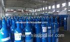
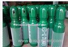
Hydrogen output: 300m3/h
working pressure: 1.6Mpa
Hydrogen purity: ≥99.999%
Moisture contained in product hydrogen:
Dew point ≤-70
4.3
Related Search
Find more related products in following catalogs on Hisupplier.com
Company Info
HANG ZHOU TAI LIAN CRYOGENIC EQUIPMENT CO., LTD. [China (Mainland)]
Business Type:Manufacturer
City: Hangzhou
Province/State: Zhejiang
Country/Region: China (Mainland)
You May Like:


Sitemap XML
About HiSupplier Help Center Customer Service Friend Links Site Map Archives
Browse by: China Suppliers - Hot Products - Products Directory - Offers Directory - Suppliers Directory - Buyers Directory
Language Option: العربية - Nederlands- Français- Deutsch- Italiano- 日本語- 한국의- Português- Pусский- Español
